
Key Points
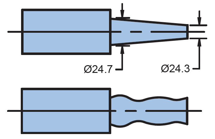
Circular runout is a 2D surface to axis control. It creates a series of 2D tolerance zones that apply independently. When applied to a cylindrical feature, each tolerance zone is the radial separation between two circles concentric with the datum axis. This controls 2D form (circularity), orientation and location to the datum axis. It does not control straightness, taper, or size, and therefore requires a separate size tolerance.
Example Drawing
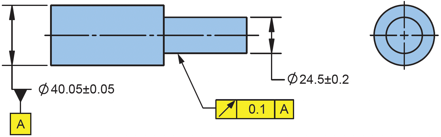
Size tolerance controls size and form (per rule#1) within 0.4.
Total runout controls orientation, location, and refines circularity within 0.1.
How to Read It
Circular runout defines a series of tolerance zones that each cross-sectional element of the surface must be within. Each tolerance zone is between two circles concentric with the datum axis, one having a radius of 0.1 larger than the other. Additionally, the feature must be within the size of 24.3-24.7.
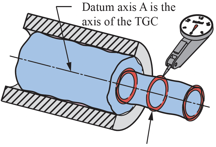
Inspection: Datum feature A is mounted in a collet or vee block. A dial indicator is placed on the surface at various locations along its length. At each location, the part is rotated about the datum axis. The full indicator movement (FIM) shall be no more than 0.1. Because this is a 2D spec, the indicator is reset at each cross-section along the length. Although the specification requires all cross-sections to be within tolerance, a quality plan should define the number of places to be verified.