Key Points
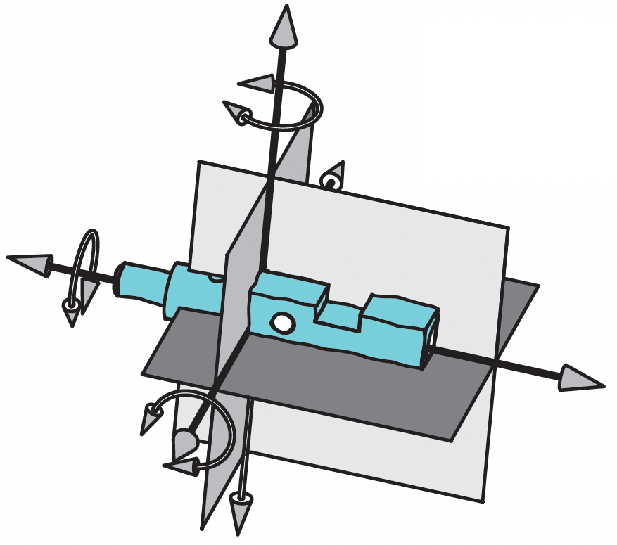
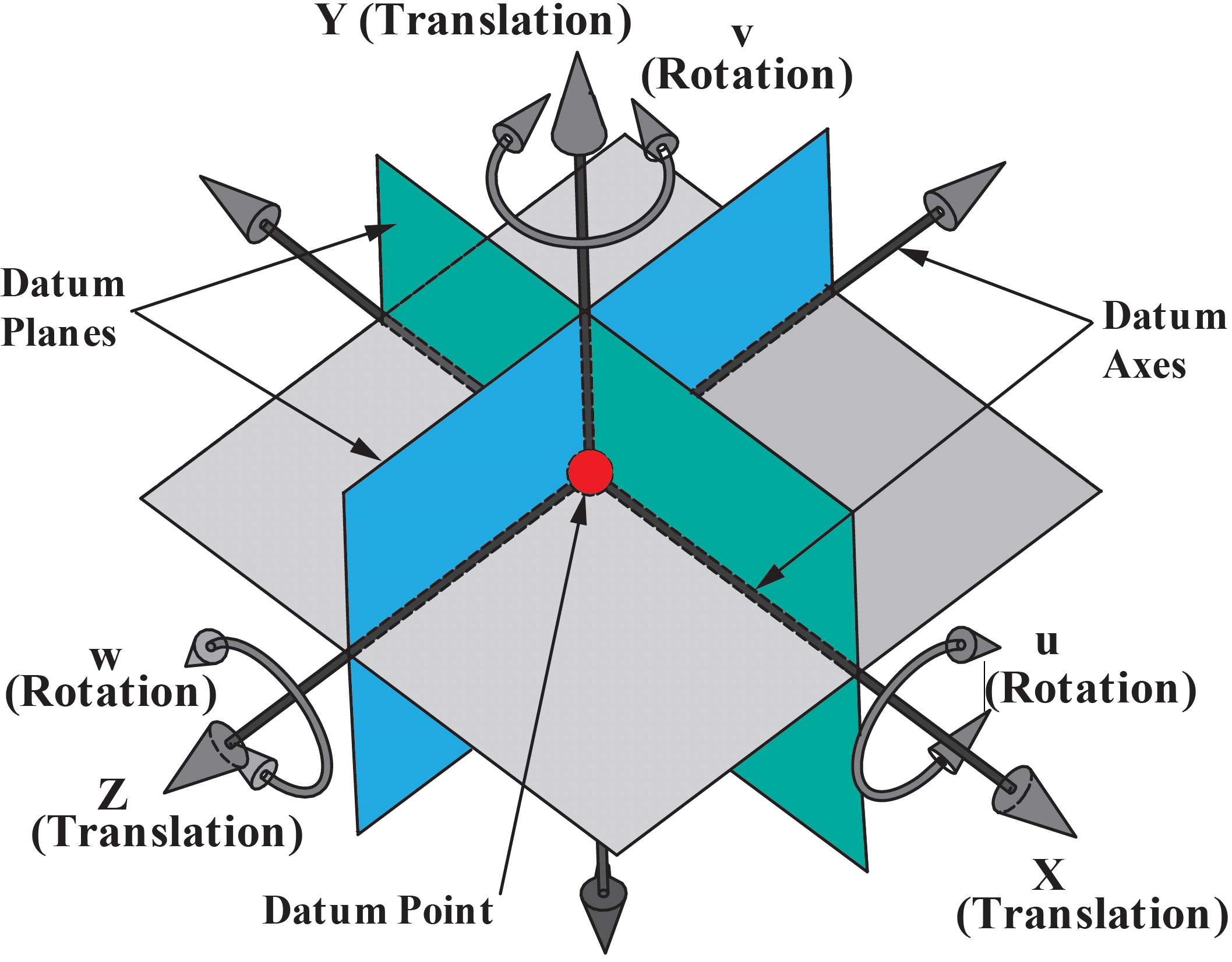
The Datum Reference Frame (DRF) consists of 3 planes, 3 axes that are mutually perpendicular and intersect at a point. The DRF is the origin of all the basic dimensions and geometric tolerances.
The DRF constrains the 6 Degrees of Freedom (DOF) of a part: three translations and three rotations. The three translations are termed X, Y and Z. The three rotations are termed u (rotation about the X axis), v (rotation about the Y axis) and w (rotation about the Z axis).
The Six Degrees of Freedom
Three Translations
X = Translation
Y = Translation
Z = Translation
Three Rotations
u = Rotation around X
v = Rotation around Y
w = Rotation around Z
Indexing a Part to a DRF
The datum features referenced in the feature control frame specify the order of how the part is aligned to the datum reference frame (DRF).
The primary datum feature is shown in the first compartment. In this example, it mates with the DRF on the highest 3 points of the surface. The secondary datum feature is shown in the second compartment and it mates with the highest 2 points. The tertiary datum feature is shown in the third compartment and it mates with the highest one point of contact.

The order of the datum feature references in the rear compartment of the feature control frame define the indexing sequence of the part to the perfect DRF.
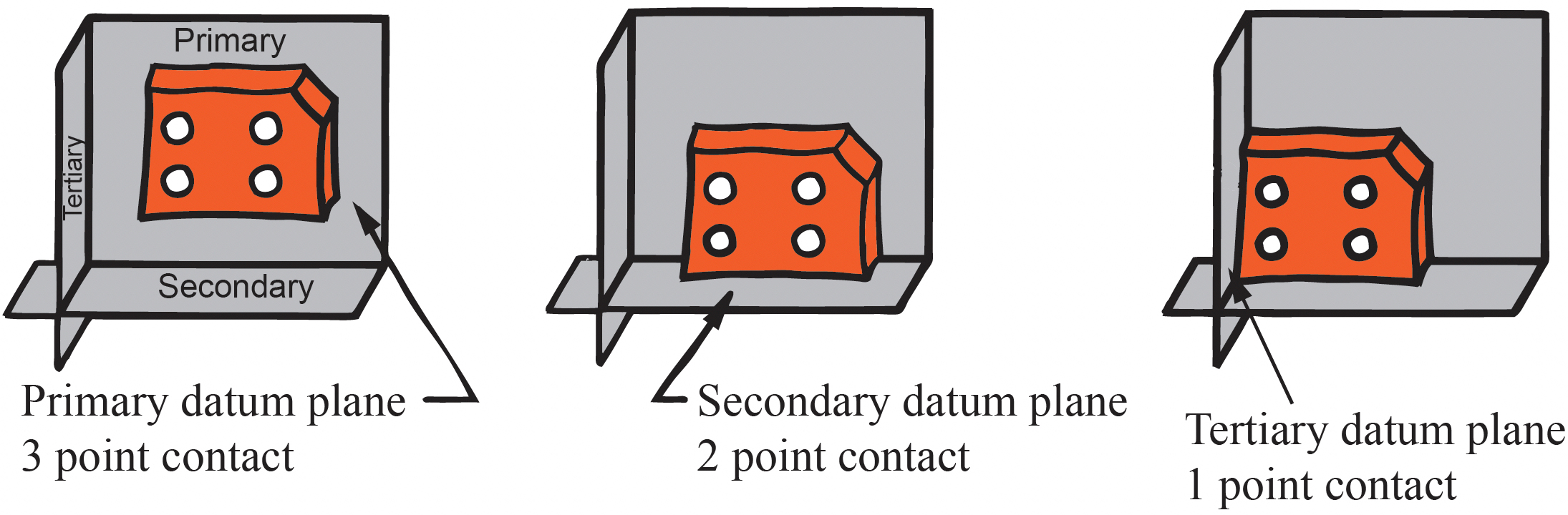
Note: Not all parts mate to the DRF with 3,2,1 points of contact. A better way to express the indexing sequence is with degrees of freedom constraints.
Degrees of Freedom – Primary Datum Feature
This table lists the possible primary datum features, the corresponding datum, and the degrees of freedom they constrain.

Datum Feature Symbols on a 3D Model
These examples illustrate how to attach datum feature symbols in a CAD model per ASME Y14.41-2019.
Datum Features without Size

When the datum feature symbol is attached to the surface, it is placed in an annotation plane perpendicular to the surface. When the symbol is attached to a leader line directed to the surface with a dot, the symbol may be placed in any annotation plane.

When multiple features are identified as a datum feature, the 2X notation is placed next to the symbol and the feature associativity is also maintained.
When a datum feature symbol is queried, the corresponding feature(s) shall highlight to show associativity.
Datum Features of Size
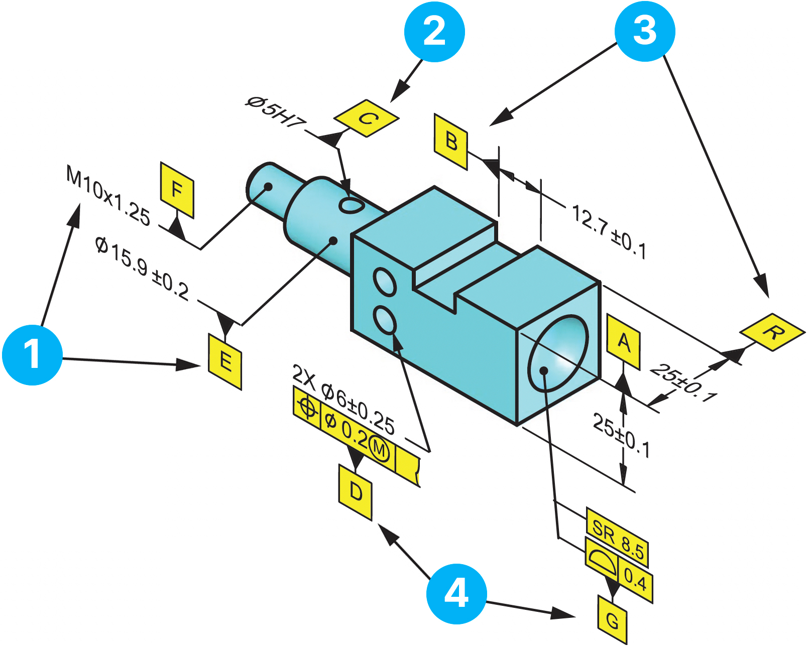
The annotation for a hole or shaft may be placed on any annotation plane when the leader line terminates on the surface with a dot.
The annotation for a hole should be placed on the annotation plane perpendicular to the feature axis when the leader line terminates with an arrow.
The annotation for a slot or width shall be placed on an annotation plane perpendicular to the feature center plane.
The datum feature symbol may be attached to the feature control frame.
Establishing a DRF on the Part
The N, E, H – DRF on the drawing
The figures below illustrate the sequence of events to establish the N, E, H datum reference frame to constrain the 6 degrees of freedom.

A lower precedence datum feature can not override the degrees of freedom already established by a higher precedence datum feature.
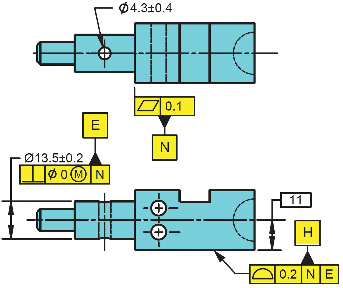
Establishing the N, E, H – DRF on the part
Datum feature N is entered in the first compartment as the primary datum feature. It establishes a plane and constrains 1 translation and 2 rotations. The surface is qualified with a flatness tolerance.
3 point contact to establish primary plane
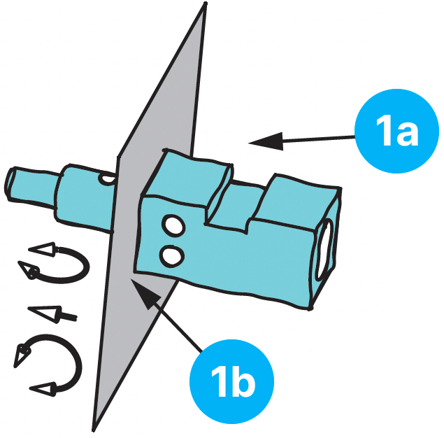

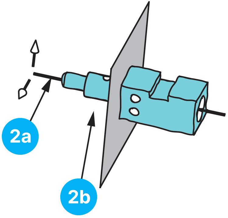
Datum feature E is entered in the second compartment as the secondary datum feature. The feature establishes an axis and constrains 2 translations. The intersection of the axis and plane establish the origin point. The feature is oriented with a perpendicularity tolerance.
3 point contact to establish secondary datum axis

Datum feature H is entered in the third compartment as the tertiary datum feature. It constrains 1 rotation. The datum feature is located relative to the origin point with a profile tolerance. The DRF is complete, and all 6 degrees of freedom are constrained on the part.