Key Points
The establishment of a Datum Reference Frame (DRF) and geometric tolerances are based on functional design requirements. Study the functional requirements below.
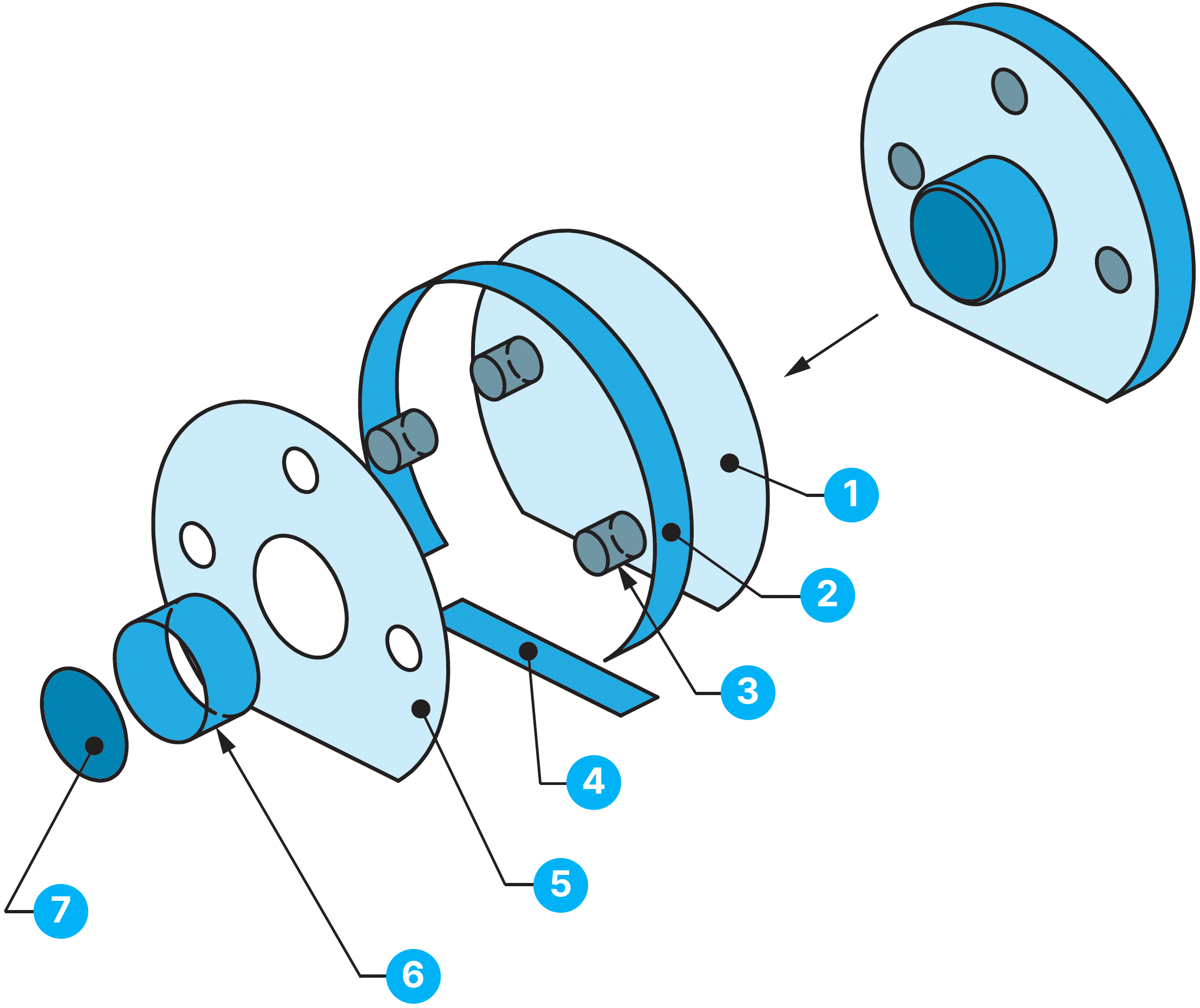
Index Assembly
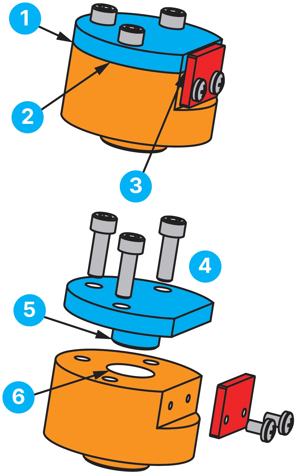
Faces must seal within 0.2
Outside cylinder edges must not mismatch more than 0.4
Flat edges must not mismatch more than 0.2
Screws must fit into holes
Bottom surface insertion must be within ±0.1
Pilot pin must fit into hole
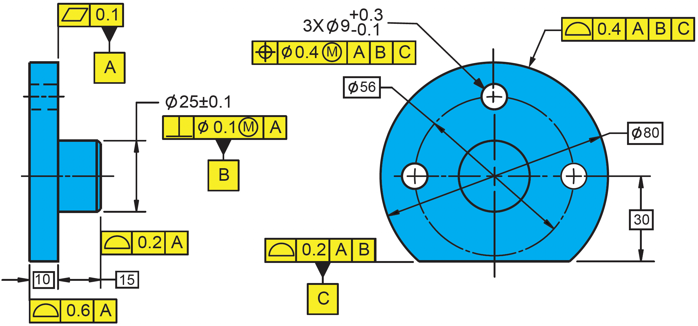
The ABC DRF is established from datum features based on mating conditions:
The three holes are given a size tolerance and position of 0.4 to the ABC DRF to align with the mating tapped holes and accept the screws.
The top surface of the pilot pin is located with a profile tolerance of 0.2 for the insertion depth requirement. The outside diameter surface is located with a profile tolerance of 0.4 for the mismatch on the outside edges. The last surface is toleranced with large profile tolerance of 0.6 because it is relatively unimportant.
Practical Example in 3D
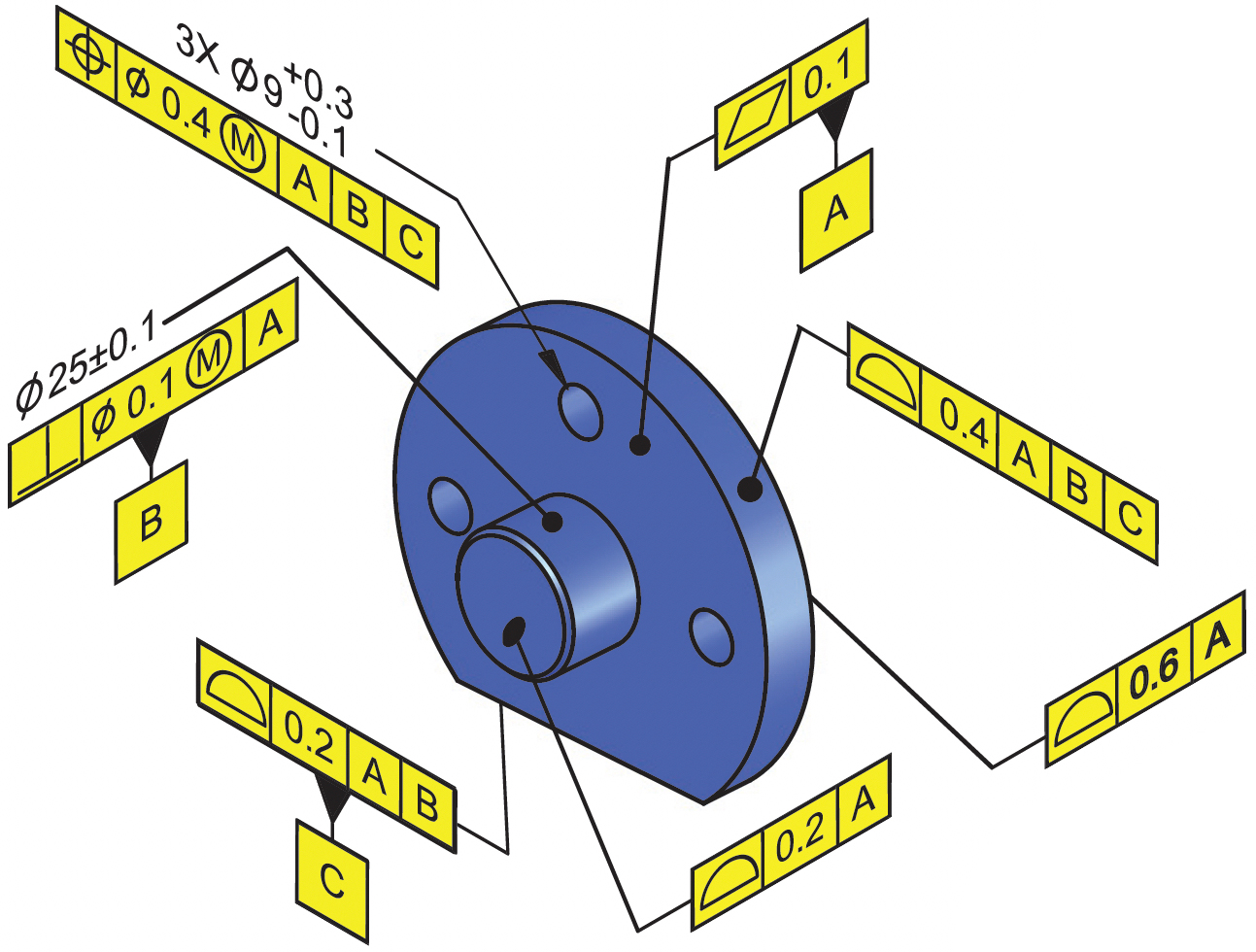
Geometric tolerancing may be applied to the Index Plate model per ASME Y14.41-2019. Basic dimensions define the geometry of the perfect model and do not need to be displayed. Each feature is toleranced with a feature control frame.
The model may be rotated in a CAD system or lightweight viewer. Each tolerance has associativity to the feature and is machine readable. When the tolerance is queried, the associated toleranced feature shall highlight.
3D Model Tolerancing
Features are the building blocks of a part, and GeoTol is a feature-based tolerancing system. The variation on these surfaces, holes, pins, slots are controlled with size and geometric tolerances. Three features are selected as datum features (A,B,C) that constrain the part and create a datum reference frame. Other features are located to this DRF with position and profile tolerances.
Every feature shall have a tolerance.
This surface located within 0.6
This surface located within 0.4
These 3 holes have size of Ø8.9-9.3 and located within 0.4
This surface located within 0.2. This is datum feature C
This surface flat within 0.1. This is datum feature A
This pin has size of Ø24.9-25.1 and perpendicular within 0.1. This is datum feature B
This surface located within 0.2