
Key Points
Position tolerance locates features of size. It defines a tolerance zone within which the feature axis or center plane must lie. The size of this zone determines the amount of variation allowed from true (theoretically exact) position. Basic dimensions establish the true position from the specified datums as well as the interrelationship between the features. See the next page for an pictorial view of the tolerance zones.
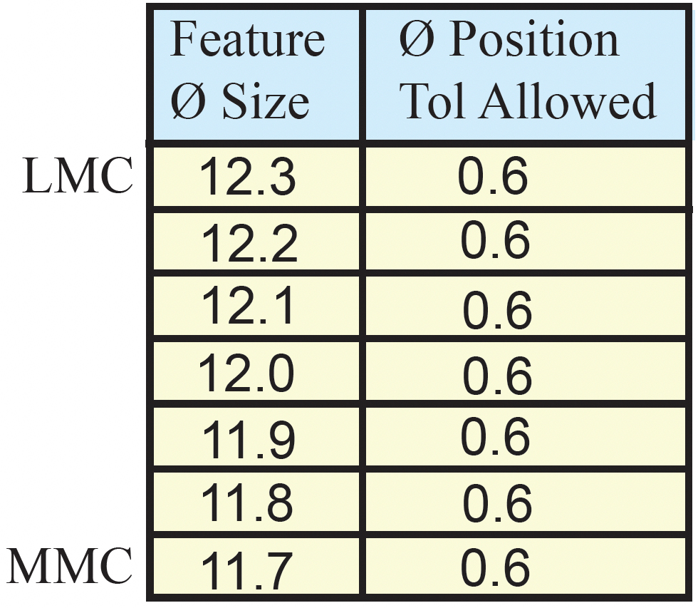
If there is no material condition modifier following the feature tolerance, the geometric tolerance applies regardless of feature size (RFS). When RFS applies, the specified geometric tolerance is independent of the actual size of the feature. The allowable geometric tolerance is limited to the specified value in the feature control frame (regardless).
Example Drawing
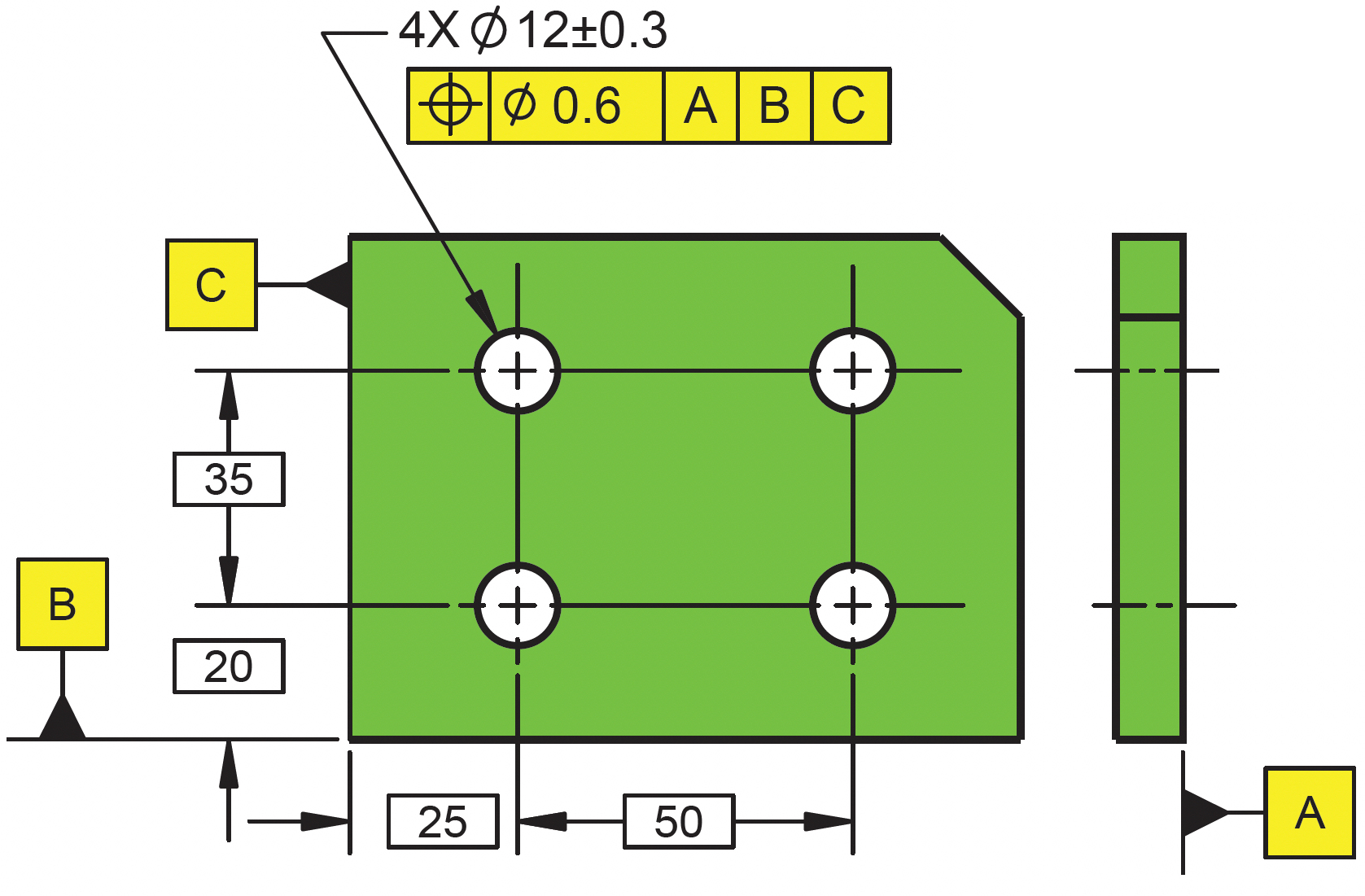
The feature control frame in this example states that the holes must be positioned within a 0.6 diameter tolerance zone. Since there is no material condition modifier following the feature tolerance, it is implied to apply RFS. This requires the axis of each hole to be positioned within a 0.6 diameter position zone despite the feature’s size. There is no additional position tolerance allowed as the holes get bigger or smaller.
How to Read It
Main view
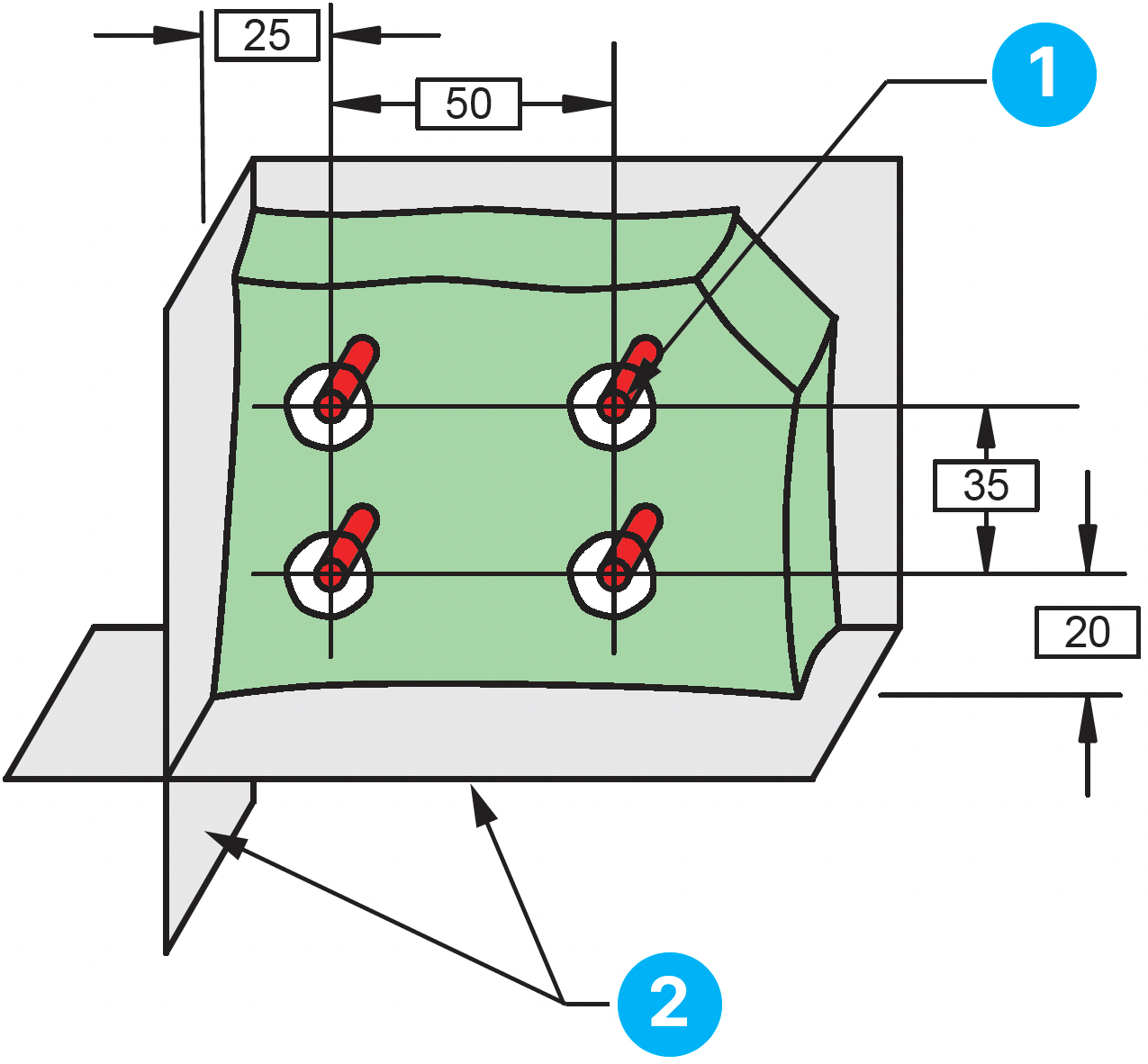
The axis of the hole must lie within a Ø 0.6 tol zone basically located and oriented to the DRF.
Datum reference frame is established on the part by datum features A, B, & C
Section view
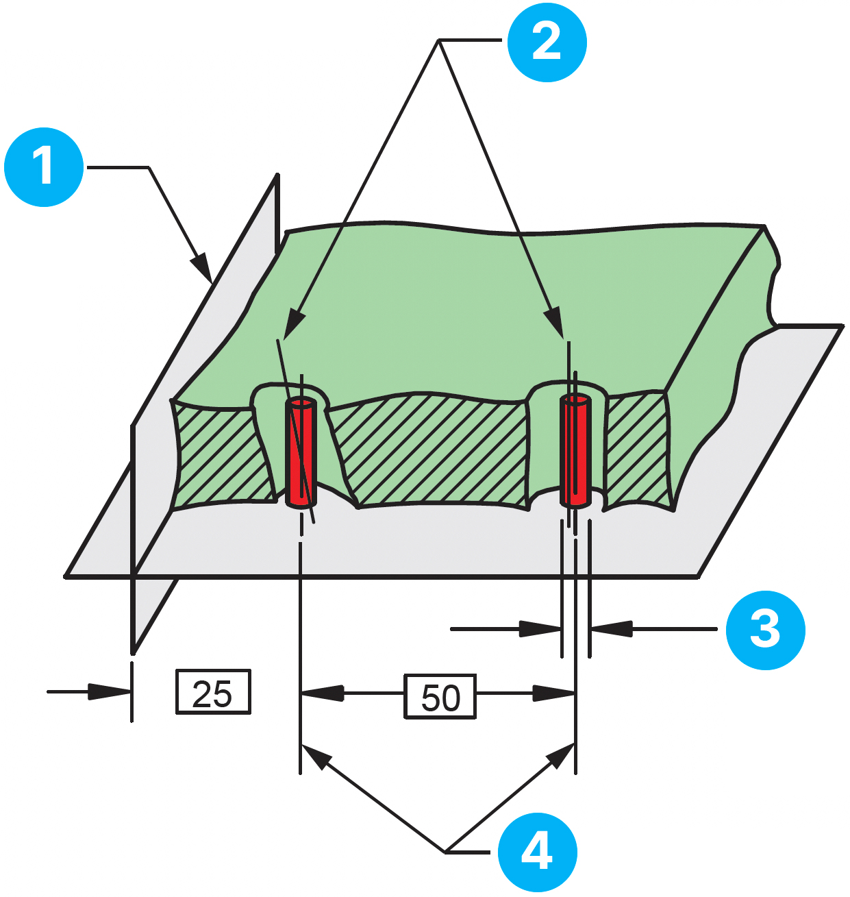
Datum reference frame
Position controls location and orientation. The axis of the hole may shift or tilt within the cylindrical zone.
0.6 cylindrical tolerance
zones. The zones extend the full height of the feature.
Tolerance zones are at theoretically exact locations from the DRF (true position).