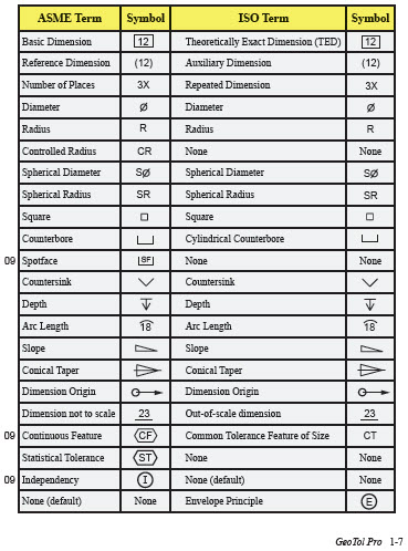
The table shows dimensioning symbols found on engineering and mechanical drawings. Note the comparison with the ISO standards. Most symbols have been in Y14.5 since at least 1994. Newer symbols introduced in Y14.5-2009 are indicated with 09 next to them. There were no new GD&T symbols in the dimensioning section in Y14.5-2018.
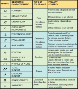
There are 12 stack-up analysis characteristics with the corresponding symbols shown. These symbols are placed in the first compartment of a feature control frame and define the geometry characteristic of the feature that is to be controlled. The characteristics are grouped into four types of tolerance: form, orientation, location, and runout. The general primary control with a few notes is also shown. This is only a quick summary and a more complete definition can be found later in the GeoTol Pro 2020 Fundamentals Workbook.
Note: Geometric characteristic symbols of concentricity and symmetry were removed in ASME
Y14.5-2018. See unit 13 in the GeoTol Pro 2020 Fundamentals Workbook for more explanation.
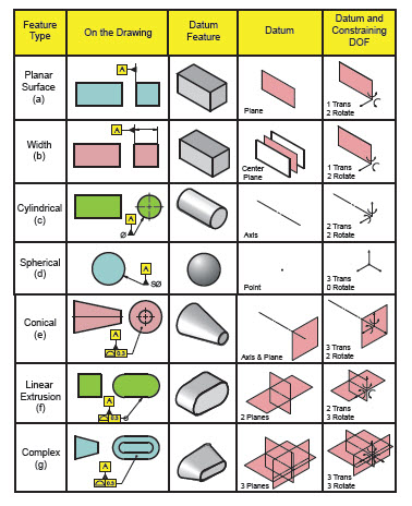
Examples of all possible types of primary datum features, their corresponding datum and constrained degrees of freedom are shown in the table.
Collections of features may also be used to establish a single datum, but for simplicity the table illustrates only single datum features.
The DOF table illustrates primary datum features only. The degrees of freedom constrained for a lower precedence datum feature depends on its geometry and order of precedence as a secondary or tertiary datum feature.