Authored by: Scott Neumann, President of GeoTol, Inc. Updated 10/3/2025
What is the latest version of ASME 14.5?
The American Society of Mechanical Engineering (ASME) has published its latest GD&T standard, Y14.5-2018. The new version does hold the title of the 2018 completion date, even though it wasn’t released until February 2019. We have been getting a lot of questions related to the ASME Y14.5-2018 and its principal changes and additions. While I can’t show every change in this article, I will outline the most notable.
Overview of ASME Y14.5-2018 Changes
At first glance, you will notice a few things in the latest version of the ASME GD&T document, but the core concepts have not changed. The extra thickness of the book seems like a lot has been added (the book went up from 214 to 326 pages), but this is mostly due to the extra 3D figures added to most of the concept sections. Y14.5 is starting to absorb the 3D representation for model-based tolerancing from the Y14.41 standard, and at least half of the 2D figures now have a matching 3D figure.
You will find minor tweaks to definitions and clarifications of concepts with new figures, as well as the removal of some outdated or misused concepts. The sections have also been renumbered to match ASME’s new formatting. Below is an outline of key takeaways:
- All new ASME standards must now start with sections 1-3 as Scope, References, and Definitions
- Procedural update: Default Stabilization for Datums
- Some concepts and GD&T symbols have been removed (notably Concentricity and Symmetry)
- Several definitions and Fundamental Rules have been revised
- Two terms have been changed: Common Datum Features and True Geometric Counterpart
- Several concepts have been expanded or clarified
- Two new symbols have been added: From-to and Dynamic Profile
- Application of tolerancing in 3D models is gaining more traction, and a lot of the definition updates in Y14.5-2018 have been to accommodate model-based applications
- The digital PDF version of the standard now has hyperlinks to the correct figures when reading text in the paragraphs, making it easier to flip between the words and figures
The Most Notable ASME Y14.5-2018 Change
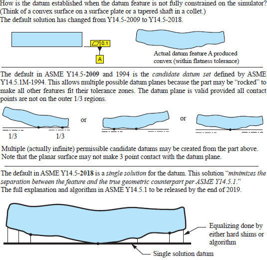
The Default Stabilization for Datums
The biggest change in the standard relates to the establishment of a datum from a datum feature that is unstable (i.e. a convex surface “that rocks”). This applies to a planar datum feature or a datum feature of size referenced at RMB. In previous versions of Y14.5, the standard used the candidate datum set to derive multiple permissible datums (find the datum that works). The 2018 version is now using a default stabilized single solution: “the part is to be adjusted to a single solution that minimizes the separation between the feature and the true geometric counterpart”. This can be done with shims on a surface plate or with an official algorithm further outlined in ASME Y14.5.1 Mathematical Definitions of Dimensioning and Tolerancing Principles to be released at the end of 2019. This default stabilization algorithm is officially called the Constrained Least Squares. This will probably have the biggest impact to industry as CMMs and other digital metrology equipment implement this new algorithm. To be honest, the candidate datum set outlined in previous versions of Y14.5 was not used in the digital equipment without the use of hard fixturing. Digitally creating a datum from an imperfect datum feature has always been a difficult problem and each CMM software programmer had their own best solution. The Y14.5-2018 has certainly helped clarify with a single stabilized solution for the digital inspection frontier. It also helps reduce tolerance stacks from form and orientation variations on datum features.
Which GD&T Symbols Were Removed and Why?
Concentricity and Symmetry
The concentricity and symmetry symbols have been removed. These two concepts shown in the 1994 and 1982 versions of Y14.5 have always been controversial and complicated. These symbols controlled the opposing median points of a feature (not the axis or center plane) relative to a datum. This is rarely a functional requirement and often gets confused with axis to axis, center-plane to center-plane requirements set by position tolerancing. These symbols were eliminated to avoid confusion and simplify the toolset.
Unequal Profile Graphical Representation
In the 2009 standard, unequally distributed profile tolerance may be indicated in two ways:
- Graphically showing the distribution with the use of a phantom line offset from the surface
- The circle U modifier in the feature control frame with a value in the added material direction
The 2018 standard has closed the door on the first graphical method. The circle U modifier is now the only way to show unequal profile tolerance. This allows easier readability in the model-based definition and digital inspection world.
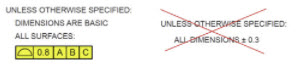
Ambiguous Plus/Minus
All plus/minus tolerances defining the relationship between features have been removed from figures and their use discouraged even more. This type of tolerancing has always been ambiguous and the Y14.5 standard did not give definitions even though some were still displayed on figures. The standard recommends the use of geometric tolerancing symbols of position, profile, orientation, and runout tolerances as the proper way to define relationship between features. This has been a long time coming, with each new version of Y14.5 removing more and more ambiguous plus/minus. I am glad to see the complete removal in 2018 even with an appendix showing the previous examples and ambiguity.
Notable Changes to Definitions
Fundamental Rules
Here is an example of a simple but important change to the Fundamental Rules:
ASME Y14.5 -2009 Paragraph 1.4 Fundamental Rules (a)
“Each dimension shall have a tolerance. The tolerance may be applied directly to the dimension (or indirectly in the case of basic dimensions) …”
ASME Y14.5 -2018 Paragraph 4.1 Fundamental Rules (a)
“Each feature shall be toleranced. Tolerances may be applied directly to size dimensions. Tolerances shall be applied using feature control frames when feature definition is basic …”
Notice the subtlety in this change. The standard is now focusing on “feature based tolerancing” rather than “dimension based tolerancing”. Plus/minus tolerances are only used to control size of features and geometric tolerances control relationships of features.
Controlled Radius
The definition of controlled radius has never been well defined:
“…The part surface shall be within this tolerance zone and shall be a fair curve without reversals. Additionally, radii taken at all points on the part contour shall be neither smaller than the specified minimum limit nor larger than the maximum limit.”
What is a “smooth faired curve”? “Radii taken at all points”? The Y14.5.1 was unable to give a mathematical definition for this. The Y14.5 committee recognized the poor definition, but was not ready to clarify or outright remove CR. A note was added in 2018 to highlight the ambiguity:
“NOTE: It is recommended that the controlled radius only be used if its meaning is clarified by a general note, a company or industry standard, or another engineering specification. This clarification should define the limits of allowable imperfections, and should be referenced on the drawing, annotated model, or elsewhere in the data set.”
Orientation of a Line Element around a Datum Axis
The 2009 standard defined the orientation of multiple line elements around a datum axis with an orientation tolerance and a note underneath: EACH RADIAL ELEMENT. The 2018 standard now shows this with a profile of a line referenced to the datum axis. This is a rarely used concept and a minor change.
Term Changes
Common Datum Features
A set of datum features used to create a single datum (notated A-B) is now called “common datum features” in 2018. This used to be called “multiple datum features” in 2009.
True Geometric Counterpart is back
The term “true geometric counterpart” in 2018 replaced “datum feature simulator (theoretical)” in 2009.
True geometric counterpart was the term used in 1994 for the theoretical device used in extracting a datum from a datum feature. This term was switched to datum feature simulator in 2009. Now 2018 has switched it back to the true geometric counterpart.
Have whiplash yet?
Expansion and Clarification of Concepts
Restrained Condition and Free State modifier
Restrained condition notes in the datum reference frame section has been expanded and clarified. Explanation of the free state modifier was also moved to this section from the form section to link the concepts. The 2018 standard gives more guidelines for the use of a restrained condition note on a non-rigid part. It lists important parameters that may be included in the note such as: magnitude, location, direction, sequence, and area of restraint. Gravity affecting a non-rigid part is addressed. Examples and rules for a restrained note and datum targets have also been added. The free state symbol may now be used on individual datum references without affecting the restraint of the rest of the part.
Axis vs Surface Interpretation for Position at MMC/LMC
In previous versions of the standard, position tolerance at MMC has been explained in terms of the feature axis within a cylindrical tolerance zone and additional (bonus) tolerance is added as the feature departs from MMC. The Y14.5 also states that position at MMC creates a virtual condition boundary that the surface may not violate. It was discovered and documented in the earlier 1994 standard that the axis interpretation and surface interpretation actual values are not equivalent because of unsymmetrical form deviations on the feature. The 1994 standard defined the surface method as the correct interpretation for position at MMC and LMC even though most of the figures showed the axis. (Note, the axis method is a more conservative interpretation and will not allow a bad part to pass.) The 2018 standard has revised a lot of figures to show the surface instead of the axis interpretation and sometimes both. Nothing has changed here in 2018 but the explanation in the figures to reduce contradictions.
Profile in a note
The 2009 standard allowed a profile to be placed in a general note by this paragraph:
3.5 FEATURE CONTROL FRAME PLACEMENT
A feature control frame is related to a considered feature by one of the following methods
(e) placing in a note, chart, or the general tolerance block
The 2018 standard has clarified this in the application of the all over profile requirement:
11.3.1.5 Profile All Over Specification:
A profile tolerance may be applied all over the three-dimensional profile of a part UOS. It shall be applied in one of the following ways:
(c) place the profile tolerance requirement in the general tolerance block or general notes
Other examples of profile blocks in notes were also included in other sections of the document. This is another push for replacement of plus/minus in title blocks to profile of a surface relative to a datum reference frame. This has been an industry practice for years. I am glad to see it added to the standard.
Runout
Runout did get a substantial overhaul in its 2018 definitions without really changing anything. In previous versions of the standard, runout was mostly defined by the dial indicator inspection device. Throughout the past decades, the Y14.5 has been transitioning out of inspection-based definitions and into more theoretical tolerance boundaries. This allows quality to choose the best inspection method based on equipment available, expertise, capability, cost and risk. Runout was the last hold-out on the inspection-based definition and was changed in 2018.
Size tolerances are added to the figures to clarify the use of size and runout together.
Tangent plane modifier is clarified for use on runout.
Runout clarified for use on assemblies that do not rotate about the datum axis.
Continuous Feature
The continuous feature symbol is first explained in 2009 and unites two or more features of size as a single feature; the size tolerance also controls coaxiality. The 2018 standard made it optional to include nX next to the CF symbol for clarification on the number of features involved. In 2009, it was a bit unclear whether this symbol could be applied to surfaces, but in 2018, there are now two types of continuous features: continuous feature and continuous feature of size. I am still unsure of the implications applying this to surfaces and it may have opened a door into a different way of controlling relationships. Some say a flatness and continuous feature may be used to control coplanarity (usually done with profile tolerance) although there are not any examples of this in the standard. It may also replace composite tolerancing in some cases. There are a couple examples in the standard of CF being used in place of 6X or 6 surfaces, but I don’t see the benefit. I worry this symbol may cause more confusion than our classic position or profile tolerances with nX or multiple leader lines to control locational relationships between features. Be careful with this slippery symbol, especially on surfaces.
New Symbols
From-to
This symbol may be used with profile tolerance in place of the between symbol. Two values are also added in the feature control frame. Instead of the profile tolerance being a fixed value across the surface, the tolerance offset gradually changes from one point to another. This same concept could have been applied in 2009 with “non-uniform profile” and sketching the boundaries. Be careful with this application. This can be complicated to understand the tolerance at any given point and should be used only in specialized situations. A single measured value for the measured data cannot be determined and the specification drops to a pass/fail requirement or variable data only.
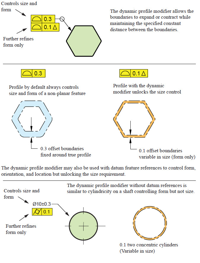
Dynamic Profile
The Dynamic Profile Tolerance modifier is the shiny new symbol in 2018. Profile has always been a powerful symbol, able to control size, form, orientation, and location based on datum references. By default, on a non-planar feature, profile will always control size and form of the surface. When this modifier is added, the profile controls the form of the feature without size. The offset between the profile boundaries remain fixed but the size of the boundaries is now variable. Profile with no datum references and the dynamic modifier would be the equivalent of cylindricity on a hole but for more complex shapes (think trianglicity and hexagonicity). Datum references may also be used with this concept to allow profile to control form, orientation, location without the size. This is usually used as a refinement of a regular profile specification. On another note, this modifier could be the solution for fixing the definition of CR.
Final Notes on ASME Y14.5-2018
I will admit, the difference between ASME Y14.5-2009 and 2018 is minor, but I do believe it clarifies and expands our toolset to control the size, form, orientation, and location of part features. Ever since the first Y14.5 standard in 1957, the committee has strived to reduce ambiguity in defining the worst-case variations of a part while also allowing maximum manufacturing tolerance. The standard has been an evolving document advancing our understanding of the subject, like a big Wiki-document passed through the generations. In addition, it has sprung new committees of recognized experts to create other related Y14 documents including mathematical definitions in Y14.5.1, measurements in B89 standards, gaging requirements in Y14.43, casting/plastic part specific symbols in Y14.8, model-based definitions in Y14.41 and Y14.47, additive manufacturing definition in Y14.46, measurement data reporting in Y14.45 to name a few.
Even though the concepts in the Y14.5 document are coming to a maturity, the work is never done. ASME Y14.5 still stands as the core document that defines the most complicated portion of documentation using engineering symbols on drawings: tolerancing!
www.geotol.com Copyright 2019.
GeoTol, Inc. is a professional training and consulting organization with 45 years of experience in geometric tolerancing and related product definition standards. GeoTol President Scott Nuemann is a member of ASME Y14.5, along with ASME Y14.5.1- Mathematical Definitions Committee, the ASME Y14.45 Measurement Data Reporting and the ASME Y14.5.2 GDTP Certification Committees and ISO TC10 committee. Partner, Al Neumann held the vice chairmanship on the development of the ASME Y14.5-2018 standard, and our professional staff are members on 15 various related ASME and ISO standards.