GeoTol Pro: A Practical Guide to Geometric Tolerancing (per ASME Y.14-2009)

$95.00

Stand-alone or companion to the GeoTol Pro 2009 GD&T Introduction Online Program, DVD Series, and the ASME Y14.5M 2009 PowerPoint Presentation.

  • 380 pages
  • hundreds of graphics in full-color
  • loaded with student exercises.
Get $10 off a workbook (ebook or printed version) with the purchase of any of the GeoTol Pro Online courses. No code needed.

    Description

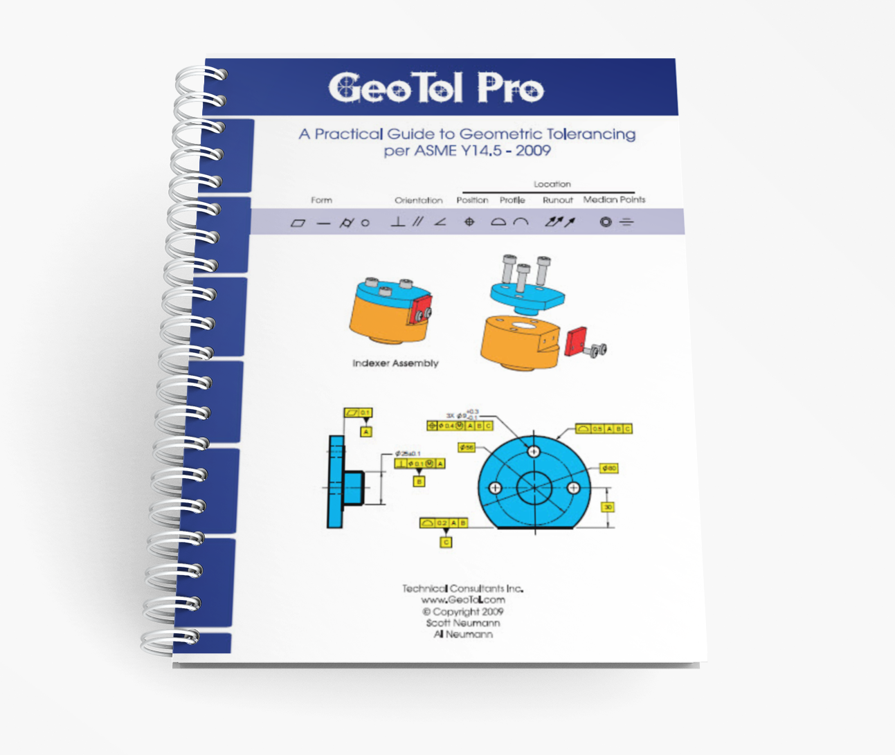
    GeoTol Pro Fundamentals Workbook (2009) Overview

    GeoTol’s practical guide to geometric tolerancing is a professional-grade, must-have companion for any personnel using GD&T. Whether you’re learning through our GeoTol Pro 2009 Online GD&T Introduction Program, presenting the GeoTol Pro 2009 Fundamentals PowerPoint to a classroom, or watching our GeoTol Pro 2009 Fundamentals DVD series, this workbook mirrors each lesson and provides space to work through every exercise. Released in mid-2009, it remains widely recognized as the “Gold Standard” for interpreting geometric tolerancing.

    Written to ASME Y14.5-2009 + ISO Alignment

    This practical GD&T workbook is written to the ASME Y14.5-2009 standard and includes:

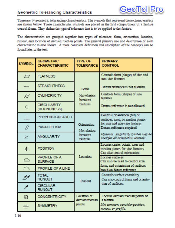
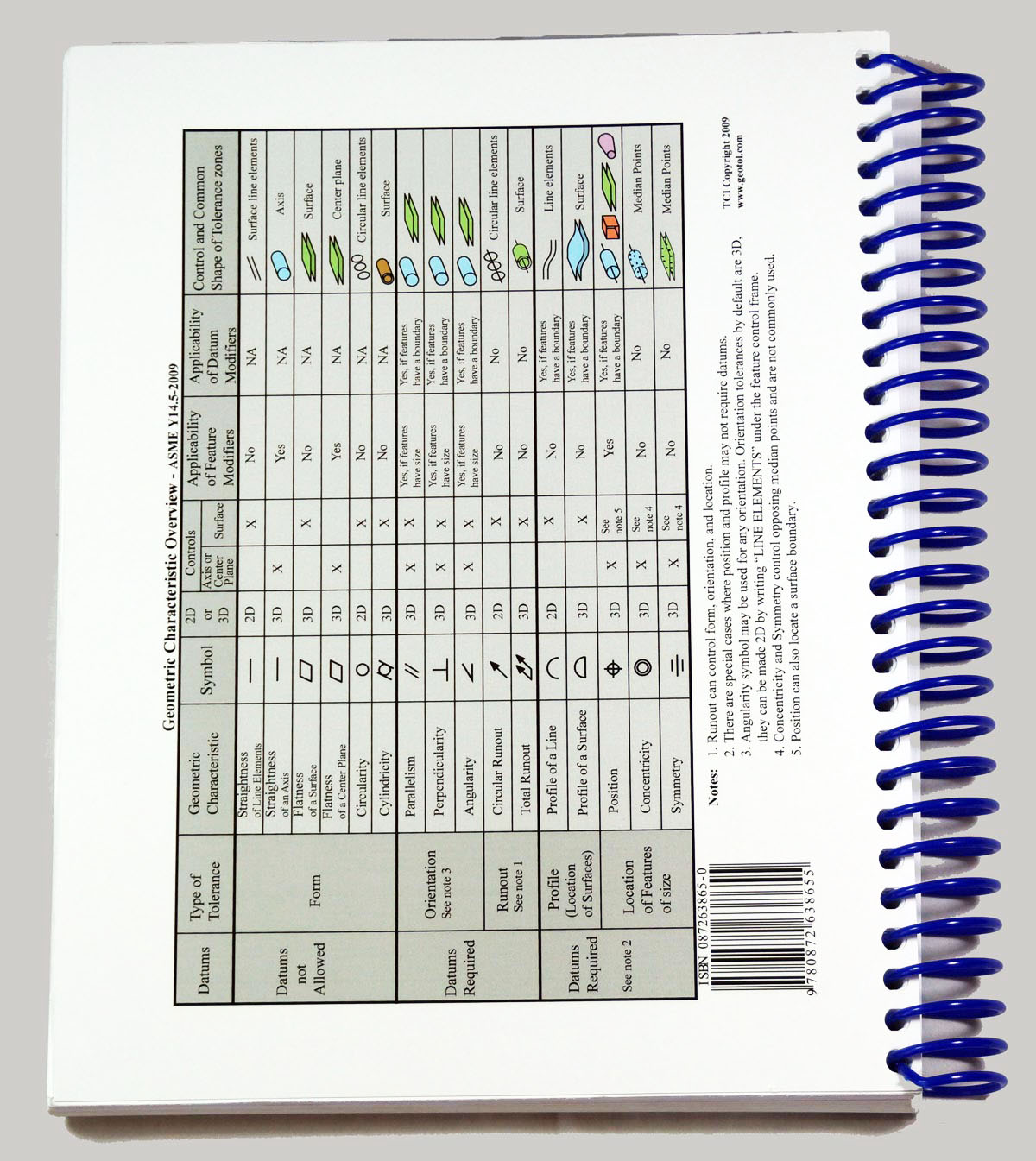
    • Symbol tables for quick reference
    • An appendix detailing improvements and changes from the ASME Y14.5M-1994 standard
    • Excerpts noting similarities and differences with relevant ISO dimensioning and tolerancing standards

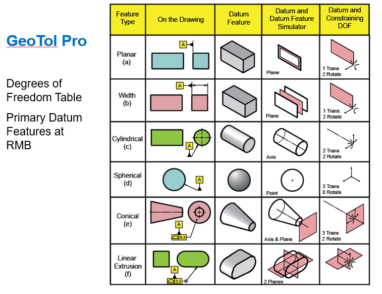
    With 380 pages and hundreds of full-color graphics, the workbook brings drawings, datum reference frames, and tolerance zones to life. The high-quality visuals make concepts clear, showing how GD&T applies to modern engineering and inspection workflows.

    Structured Learning From Fundamentals to Advanced Concepts

    Written in simple, easy-to-understand language, the workbook features 17 units that guide learners from the basics of GD&T through advanced concepts such as:

    • Tolerance boundaries
    • Simple stack-up calculations
    • Graphical inspection techniques
    • Data reporting procedures

    Hundreds of detailed illustrations show parts in real assemblies, demonstrate drawing applications, and simplify inspection methods. Exercises appear during and at the end of each chapter, allowing students to test their new skills as they progress. A full table of contents and index support quick information lookup.

    Ideal for engineers, designers, manufacturing professionals, and quality personnel, the GeoTol Pro Fundamentals Workbook (2009) provides practical knowledge applicable across industries.

    Instructor-Friendly Features

    GeoTol Pro: A Practical Guide to Geometric Tolerancing can be used on its own or as part of a complete GD&T training system. Other resources for instructors and training leaders that GeoTol offers:

    Together, these materials give instructors the ability to create an engaging, hands-on learning environment that blends visual, physical, and digital teaching tools.

    About the Authors

    The GeoTol Pro Fundamentals Workbook 2009 is co-authored by Scott Neumann and Al Neumann, leading experts in geometric tolerancing.

    • Scott Neumann
      • Mechanical engineer specializing in tolerance stack-ups and inspection techniques
    • Al Neumann
      • Member of the ASME Y14.5 committee for over 30 years
      • Serves on the ASME Y14.5.1 committee on mathematical principles of dimensioning and tolerancing

    Both authors are active contributors to ISO standards committees and have written best-selling books and video training programs on GD&T. Together, they have delivered thousands of training programs to hundreds of thousands of professionals worldwide. Their combined experience across hundreds of industries is embedded throughout the workbook, making it a trusted resource for learning and applying geometric tolerancing.

    View Outline

    GeoTol Pro 2009 Workbook
    Unit 1 Introduction – Symbols and Terms
    Unit 2 Limits of Size
    Unit 3 How the Geometric System Works Part 1&2
    Unit 4 Position Verification
    Unit 5 Product Plans and Virtual Condition
    Unit 6 The Datum Reference Frame I
    Unit 7 Datum Feature Modifiers
    Unit 8 The Datum Reference Frame II – Targets and Irregular Surfaces
    Unit 9 The Datum Reference Frame III – Advanced Concepts
    Unit 10 Form Tolerances
    Unit 11 Orientation Tolerances
    Unit 12 Profile Tolerances Part1&2
    Unit 13 Position Tolerances
    Unit 14 Coaxial Tolerances
    Unit 15 Fastener Formulas and Screw Threads
    Unit 16 Boundaries
    Unit 17 Application Exercises

    Detailed Outline

    • Unit 1: Introduction to Geometric Dimensioning and Tolerancing
      • General overview, geometric characteristic symbols, rules, terms and definitions
      • Introduction to measurement principles, open set-up and CMM
    • Unit 2: Limits of Size
      • Rule #1
      • Features with & without size
      • Regular & irregular features of size
      • Independency principle
      • Limits & fits
    • Unit 3: How the Geometric System Works
      • Problems with plus/minus tolerancing
      • Introduction to the datum reference frame
      • Datum precedence
      • Basic dimensions
      • Introduction to Position Tolerancing
      • MMC, LMC, RFS feature modifiers
      • Introduction to Profile Tolerancing
    • Unit 4: Position Tolerancing and Verification
      • Verifying position
      • More on MMC, LMC, RFS feature modifiers
      • Paper gage
    • Unit 5: Product Plans and Virtual Condition
      • Product definition drawing, manufacturing process plan, dimensional measurement plan
      • Introduction to boundaries
      • Calculating virtual size
      • Perpendicularity as a refinement of position
    • Unit 6: The Datum Reference Frame
      • Datums, datum features, datum feature simulators
      • Holes, slots, shafts, tabs, widths as datum features
      • Connection between the theory and physical
      • Datum feature precedence
      • Constraining the degrees of freedom
      • Datum feature simulator requirements
      • Partial datum features
    • Unit 7: Datum Feature Modifiers
      • MMB, LMB, RMB
      • Calculating boundaries for datum features at MMB
      • Comparison between datum feature modifiers RMB and MMB
      • Simultaneous requirement implied as default
      • Calculating allowable datum feature shift
      • Paper gage calculations
    • Unit 8: Datum Targets and Irregular Surfaces
      • Contoured datum features
      • Datum targets used on sheet metal
      • Datum targets used on castings
      • Calculations from casting to machining
    • Unit 9: Datum Reference Frames, Advanced Topics
      • Hole patterns as datum features
      • Hole and Slot design
      • Translation modifier
      • Multiple DRF
      • Customized DRF
    • Unit 10: Form Tolerances
      • Flatness, Straightness, Circularity, Cylindricity
      • Flatness per unit area
    • Unit 11: Orientation Tolerances
      • Perpendicularity, Parallelism, Angularity
      • Orientation as a refinement of Location
      • Perpendicularity of Zero at MMC
    • Unit 12: More Advanced Profile Tolerances
      • Profile of a surface and line
      • Using profile to control size, form, orientation and location
      • Bilateral and unilateral tolerances
      • Application and verification princip
      • Free state and restrained condition
      • Composite profile
    • Unit 13: More Advanced Position Tolerances
      • Position rectangular, conical, spherical tolerance zones
      • Position boundary
      • Continuous feature
      • Composite position tolerancing
      • Comparison of two single segments vs. composite tolerancing
      • Paper gage calculations
    • Unit 14: Coaxial and Runout Tolerances
      • Two datum features creating a single datum axis (A-B)
      • Position to control coaxiality
      • Circular runout and total runout
      • Concentricity and Symmetry
      • Profile to control coaxiality
      • Comparison of position, concentricity, runout, profile
    • Unit 15: Fixed and Floating Fastener Formulas
      • Calculating position tolerances for clearance holes and tapped holes
      • Screw threads with projected tolerance zones
    • Unit 16: Boundaries
      • Maximum material boundary, least material boundary, inner boundary, outer boundary
      • Introduction to stack ups
      • Calculations for wall thickness
    • Unit 17: Applications
      • Corner Bracket
      • Flange Bearing
      • Powder Case
      • Link

    View Sample

    You may also like…

    • GeoTol Pro 2009 Fundamentals of Geometric Dimensioning and Tolerancing
    • GeoTol Pro Fundamentals Pocket Guide (pack of ten) 2009