Description
Our GeoTol Pro 2020 Instructor PowerPoint has all the graphics from the accompanying GeoTol Pro 2020 Fundamentals Workbook. The slides are split into the same 14 units as the workbook and the leader may create a custom lesson plan by hiding slides or adding your own content. Instructor notes are included at the bottom of each slide as a guide. A lot of the graphics are animated to show tolerance zones and inspection methods. Save yourself hundreds of hours of slide prep with this ready-made package. GD&T basics training ppt comes in USB format.
View Outline
Unit 1: Introduction to Geometric Dimensioning and Tolerancing
General overview, geometric characteristic symbols, rules, terms and definitions; Introduction to measurement principles, open set-up and Coordinate Measuring Machine (CMM)
Unit 2: Limits of Size
Rule #1; Features with & without size; MMC and LMC; Why plus/minus tolerancing is confusing; The need for geometric tolerancing
Unit 3: How the Geometric System Works
Introduction to the datum reference frame; Basic dimensions; Introduction to Position Tolerancing; Square vs Round tolerance zones; MMC, LMC, RFS modifiers; Introduction to Profile Tolerancing
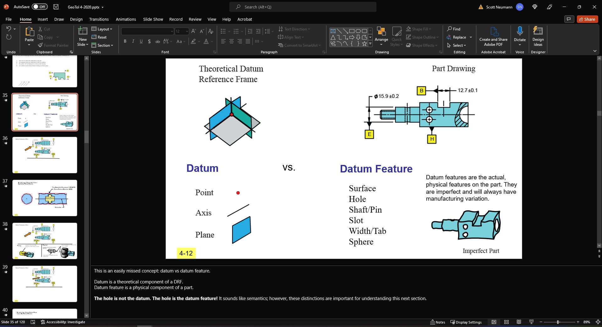
Unit 4: The Datum Reference Frame
Datums, datum features, true geometric counterparts; Holes, slots, shafts, tabs, widths as datum features; Connection between the theory and physical; Datum feature precedence; Constraining the 6 degrees of freedom; True geometric counterpart requirements; Partial datum features
Unit 5: The Product Plans and Position Tolerancing Verification
Difference between the product drawing, manufacturing process plan, and dimensional measurement plan; The engineering specification versus the inspection method; Verifying position with MMC and RFS modifiers; Intro to paper gage
Unit 6: Orientation Tolerances
Perpendicularity, Parallelism, Angularity; Orientation as a refinement of location; Inspection reporting: The GD&T hierarchy of tolerances
Unit 7: Virtual Condition and Material Boundary Modifiers
Introduction to boundaries; Calculating virtual condition; Material boundary modifiers MMB, LMB, RMB; Calculating boundaries for datum features at MMB; Comparison between RMB and MMB; Simultaneous requirement; Calculating allowable datum feature shift; Paper gage calculations
Unit 8: Datum Targets and Irregular Surfaces
Angled datum features; Contoured datum features; Datum targets for sheet metal; Datum targets for plastic parts; Datum targets for castings and calculations to machining; Free state and restrained condition
Unit 9: Advanced Datum Reference Frames
Two datum features creating a single datum axis (common datum features, A-B); Coaxial holes as datum features; Hole patterns as datum features; Hole and slot design; Multiple datum reference frames;
Unit 10: Form Tolerances
Flatness, Straightness, Circularity, Cylindricity; Average diameter; Flatness per unit area
Unit 11: Advanced Profile Tolerances
Profile of a surface and line; Sample application drawings; Unequal and unilateral tolerances; verification principles and measurement data reporting; Composite profile; Coplanarity
Unit 12: Advanced Position Tolerances
Floating fastener formula; Fixed fastener formula; Position rectangular, conical, spherical tolerance zones; Position boundary; Continuous feature; Composite position tolerancing; Paper gage calculations
Unit 13: Coaxial and Runout Tolerances
Coaxial controls – Comparison of position, circular runout, total runout, concentricity, and profile
Unit 14: Practice drawings for GD&T application
Additional: Updates from ASME Y14.5-2009 (or 1994) to Y14.5-2018